Learn How to Use OpenSCAD Software with Helpful i.materialise Tutorial and How-To Videos

![]() If you prefer creating your own 3D models, instead of downloading and printing open-source designs, the most important aspect, when choosing your preferred 3D modeling software, is how easy the process is. You can’t create successful 3D prints if you’re spending more time trying to decipher the program than you are modeling. While we all have our favorites, from ImplicitCAD to SketchUp, OpenSCAD is always a popular choice: we’ve written about many objects that were created using this free CAD software, like these Magic: The Gathering tokens. OpenSCAD was created in 2009 and allows users to create their own 3D models. It is definitely more focused for small parts, and not for organic structures or art projects. The versatile program is available for download through Windows, Mac, and Linux.
If you prefer creating your own 3D models, instead of downloading and printing open-source designs, the most important aspect, when choosing your preferred 3D modeling software, is how easy the process is. You can’t create successful 3D prints if you’re spending more time trying to decipher the program than you are modeling. While we all have our favorites, from ImplicitCAD to SketchUp, OpenSCAD is always a popular choice: we’ve written about many objects that were created using this free CAD software, like these Magic: The Gathering tokens. OpenSCAD was created in 2009 and allows users to create their own 3D models. It is definitely more focused for small parts, and not for organic structures or art projects. The versatile program is available for download through Windows, Mac, and Linux.
 3D printing service i.materialise is a fan of the software. In fact, it recently posted an “OpenSCAD Tutorial & Cheat Sheet: Getting Started with a Free CAD Software” tutorial in the company blog. Using step-by-step instructions, a cheat sheet, and four helpful videos, you can learn how to use the powerful software, and how to create your first model for 3D printing.
The blog notes that David, with i.materialise, is running the tutorial. In his first video for “Part 1 – Introduction to OpenSCAD, Resizing, Moving, Subtracting,” he explains how OpenSCAD actually works, and teaches you about the basic commands. The complex shapes you can create using the software are made up of a large amount of “primitives,” which are simple 3D shapes like cubes and spheres. You can move the primitives around in a three-dimensional space, and do all sorts of things: rotate them, rescale them, add them together or subtract them (to make cut-outs and holes in your model). This creates complex 3D models.
The tutorial states, “Think about an OpenSCAD 3D model like a LEGO project. In order to create a stunning design, you just have to use the right LEGO bricks in the right places.”
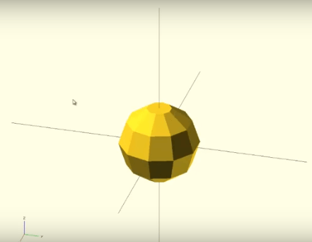 When you begin working on a new design in OpenSCAD, the split-screen interface automatically comes up. The left-hand side is called the editor, or console, and instead of drawing shapes using your cursor, that’s where you type your commands. The right-hand side shows the result of your typed command as a 3D model. So for example, if you type “sphere3” into the editor, you’ll see a sphere, with the dimensions 3 x 3 x 3 mm, pop up on the right-hand side of your screen.
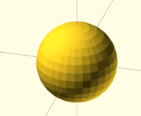 If you want to make the sphere look cleaner and more, well, sphere-like, you can type the command “$fn=30” to make your sphere out of 30 different parts. To make a flatter cylinder, instead of a taller one, you can specify the radius and height of the primitive separately, but still in the same command, using “cylinder (r = 5, h = 1).” You can also always see the X, Y, and Z axes displayed, down in the lower left-hand corner of the right-hand side of the screen.
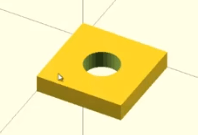
Once you’ve learned some of the more basic OpenSCAD commands, you’re ready to create a simple 3D print! You accomplish this by “putting simple primitives into the bigger picture and creating a simple functional 3D printable object.” For example, in his video tutorial, David subtracts the shape of a cylinder to create a plate with a hole in it. You can create a cube, and then create a separate cylinder, and use the “translate” command to put the cylinder “inside” the cube. Remember, typing an exclamation mark in front of the cylinder will let you see only the cylinder, and not the cube.
 As soon as you’re able to use the difference operation to cut out holes in your models, you’ll learn how to resize and rotate your objects, and why it’s helpful to “name” a group of primitives. Finally, you’ll learn how to use flexible variables, like length, thickness, and width, to design objects. Variables can be changed very quickly, and while they’re not always necessary for simple designs, this is an important skill to master, as it makes editing complex models much easier.
Now you know how to create a complex object by “patching primitives together.” It’s time you learned why copying and pasting is useful, like using two copies of a plate in order to create a right angle bracket. Instead of just putting primitives together, you’re now putting complex objects together to create sophisticated designs. But it’s not quite as simple as typing Control C and Control V!
David says, “The thing about OpenSCAD is you have to think very carefully about what you want to do before you do it.”
He explains how copying, pasting, and rotating your objects works in his short video; take a look:
Finally, David’s last video will teach you how to create a 3D model for a simple motor mount, which looks sort of like a square piece of cheese. He first explains what exactly the holes in the motor mount do: for example, the largest hole is “where the output shaft will stick through.”
“This is a fairly simple part, you’re just gonna have the difference of a cube with a couple cylinders for your holes. The only important thing, obviously, is that everything be the right size and the right place,” David explains.
His video guides you through the process, and also “focuses on how you can use a variable to your advantage and how to set the perfect values for units.”
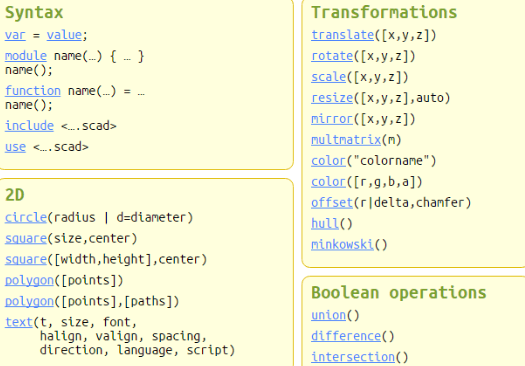 There are a lot of OpenSCAD commands to remember, otherwise you will have a pretty hard time creating anything, much less a complex part. But luckily, there is an OpenSCAD ‘cheat sheet’ that summarizes all of the commands you’ll need to create your own 3D model. Remember, once you’ve learned how to use OpenSCAD and have successfully created a 3D model, you can use 3D printing services, just like i.materialise, to complete a high-quality print.
Visit this original blog post to see all four of David’s helpful videos! Discuss in the OpenSCAD forum at 3DPB.com.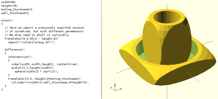
Subscribe to Our Email Newsletter
Stay up-to-date on all the latest news from the 3D printing industry and receive information and offers from third party vendors.
You May Also Like
3D Printing News Briefs, April 13, 2024: Robotics, Orthotics, & Hypersonics
In 3D Printing News Briefs today, we’re focusing first on robotics, as Carnegie Mellon University’s new Robotics Innovation Center will house several community outreach programs, and Ugogo3D is now working...
Rail Giant Alstom Saves $15M with 3D Printing Automation Software 3D Spark
3D Spark has entered into a three-year deal with the rail giant Alstom. Alstom, a transport behemoth with annual revenues of $16 billion, specializes in the manufacture of trains, trams,...
Meltio Expands Global Reach with New Partnerships in the Americas and Europe
Spanish 3D printing manufacturer Meltio has expanded its sales network across the globe. With the addition of three new partners in the United States, Brazil, Argentina, and Italy, Meltio aims...
3D Printing Webinar and Event Roundup: April 7, 2024
Webinars and events in the 3D printing industry are picking back up this week! Sea-Air-Space is coming to Maryland, and SAE International is sponsoring a 3D Systems webinar about 3D...